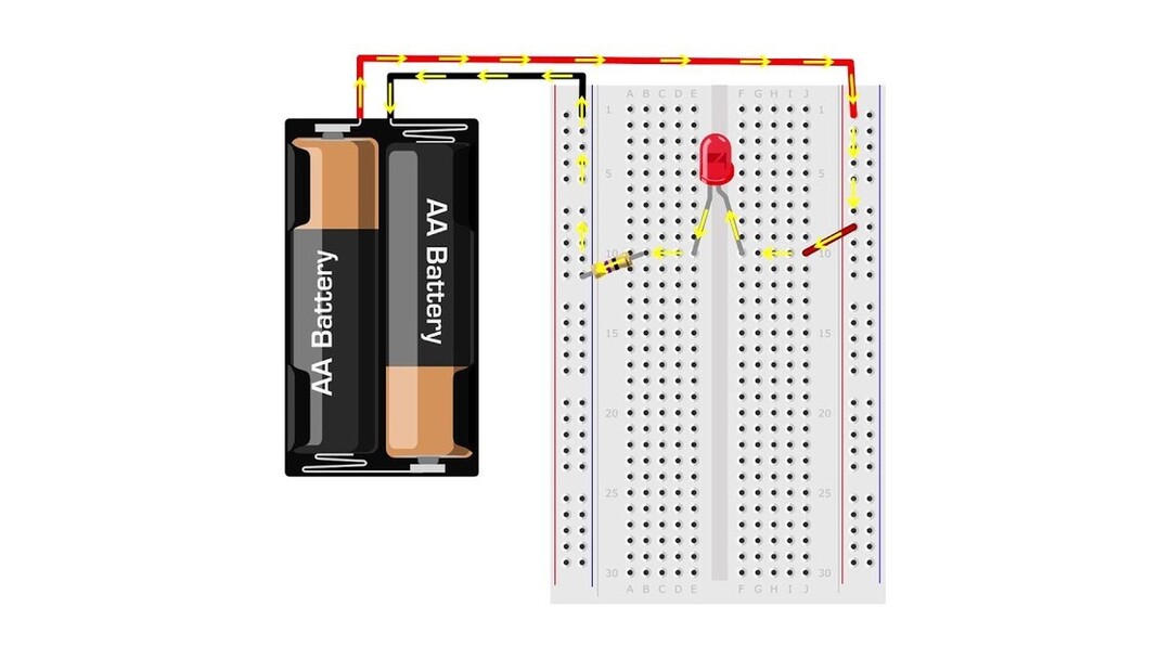
If you’ve ever snapped together a battery pack and watched an LED light up, you’ve already built a circuit. A circuit is simply a complete loop that lets electrical energy move from a power source, through components that do something useful, and back to the source again. When the loop is complete, power can flow. When the loop is broken, everything stops. That one idea is the secret behind most beginner electronics kits, from blinking lights to tiny buzzers and spinning motors.
What a Circuit Really Is (In Plain English)
Think of a circuit like a track for energy. The battery (or USB power) provides the push. Wires or metal traces provide the path. Components along the path use that energy to make something happen, like light, sound, motion, or signals. Then the energy returns to the battery to complete the loop.
A helpful way to learn the basics is to explore a beginner-friendly circuit lesson like SparkFun’s guide to voltage, current, and resistance or the visuals in Khan Academy’s electrical engineering basics.
The Three Big Ideas: Voltage, Current, and Resistance
Most kit projects make more sense once you know these three words. You don’t need advanced math to understand what’s happening, just a solid mental picture.
Voltage: The “Push”
Voltage is what gives electricity the motivation to move. A 9V battery has more “push” than a 3V coin cell. That doesn’t automatically mean it’s better for every project. Some parts, like LEDs or small sensors, only want a little push. Too much voltage can overheat or damage components.
Current: The “Flow”
Current is the amount of electricity flowing through the circuit. In kid-friendly projects, the current is usually small, but it still matters. If too much current tries to flow through a component, it can get hot or burn out. That’s why many electronics kits include resistors. They keep current at a safe level.
Resistance: The “Control”
Resistance is what slows the flow down. A resistor acts like a tiny gatekeeper. In many beginner builds, the resistor protects an LED from getting too much current. If you want a deeper (but still understandable) explanation, All About Circuits is a great reference.
Why Circuits Need a Complete Loop
This is the most common “why won’t it work?” moment in beginner electronics: the circuit isn’t a loop. Maybe a wire isn’t connected. Maybe a component is placed one hole off on the breadboard. Maybe a switch is off. When the loop is broken anywhere, current can’t flow, and the project won’t turn on.
A switch is actually a perfect example of this. When the switch is OFF, the circuit is open, meaning the loop is broken. When the switch is ON, the circuit closes, making a complete loop so current can move again.
Series vs Parallel: Two Ways to Connect Parts
Electronics kits often use two common circuit styles: series and parallel. Learning the difference helps you predict what will happen before you even power up your build.
Series Circuits
In a series circuit, components are connected in a single line, one after another. Current flows through the first component, then the next, then the next. If one part is disconnected or fails, the whole circuit stops, because the loop is broken. Many simple beginner projects start in series because it’s easy to see the path.
Parallel Circuits
In a parallel circuit, components are on separate branches. Current has more than one path to follow. This is useful when you want multiple parts to work independently. For example, if one LED in a parallel setup stops working, the others can still stay on because their paths are separate.
In real life, many devices mix series and parallel sections. Even kid-friendly kits start doing this once you add more lights, sensors, or motors.
How Breadboards Help You “See” a Circuit
Breadboards are one of the best learning tools for kids because they let you build and rebuild without soldering. Under the plastic, metal strips connect certain holes together. That means some holes are already connected behind the scenes, acting like built-in pathways for your circuit.
If a project isn’t working, a breadboard wiring mistake is a usual suspect. A wire might look close enough, but if it’s in the wrong row, it’s basically not connected at all. Many kits include a diagram showing exactly where each wire should go, and it’s worth following it closely until you’re confident.
Polarity: Why Direction Matters
Some components care which way they are placed. This is called polarity. LEDs are the classic example. Put an LED in backwards, and it usually won’t light. Motors, certain capacitors, and some sensors also have polarity rules. Kits often label the positive and negative sides to help you avoid guessing.
If your project doesn’t work, it’s smart to check polarity early. It’s one of the easiest fixes once you know to look for it.
A Simple Example: Battery + Switch + Resistor + LED
Let’s walk through a classic beginner circuit. The battery provides voltage. The switch controls whether the loop is open or closed. The resistor limits current so the LED stays safe. The LED converts electrical energy into light. When the switch closes the loop, current flows through the resistor and LED, and the LED turns on.
If the LED doesn’t light, you can troubleshoot in a logical order. First, check that the battery is connected. Next, make sure the switch is ON and actually placed correctly. Then confirm the LED direction. Finally, check that the resistor is connected in the right spots and the wires match the diagram. This “check the loop” mindset is how real engineers debug real devices.
Common Beginner Mistakes (And Easy Fixes)
Most beginner circuit problems come from small setup errors, not “bad parts.” A wire in the wrong hole, a loose connection, or a backward LED can stop the whole build. The good news is that these mistakes are part of learning, and each fix teaches you how circuits behave.
One of the best habits kids can build is to change only one thing at a time when troubleshooting. If you move five wires at once, it’s hard to know what actually fixed it. If you change one thing, you learn what mattered.
How This Connects to Real Technology
The same circuit rules that power a simple LED project also power phones, game controllers, tablets, and robots. Those devices just contain many circuits working together. Inside, you’ll find power circuits, sensor circuits, audio circuits, and tiny “decision-making” circuits built around microcontrollers. Electronics kits are like a beginner version of that world: small, understandable, and hands-on.
Next Steps: What to Build After You Understand the Flow
Once you understand how power flows through a loop, you’re ready for projects that feel like real gadgets. Try builds that include a light sensor, a button-controlled buzzer, or a motor that turns on when you flip a switch. You’ll start noticing patterns: power in, control, component action, power back. That pattern is the heartbeat of electronics.
If you want a fun next lesson, look up simple “Ohm’s Law” demos using safe kit parts, or follow a beginner project library like SparkFun Learn to keep building your skills one project at a time.
With every build, circuits get less mysterious and more like a puzzle you know how to solve. And that’s the best part: once you understand the flow, you’re not just following instructions anymore—you’re learning how technology actually works.