When you first begin exploring electronics, electricity feels like a simple force that powers your components. You plug in a battery, and an LED lights up or a motor spins. But as your projects advance, you quickly realize that electricity does more than just provide power. It carries information. To understand how circuits communicate, you need to understand how they use that electricity to send messages.
In the world of electronics, information is sent using two primary languages. Knowing how to tell these two languages apart is one of the most important steps in designing smarter, more interactive projects. Understanding analog vs digital signals changes the way you look at sensors, microcontrollers, and your breadboard wiring entirely.
The Core Difference Between Two Worlds
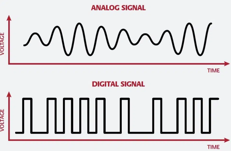
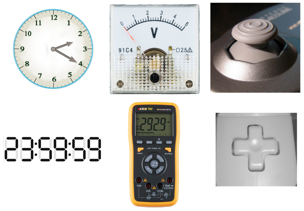
The easiest way to understand the difference between these two signals is to look at how you control the lights in your house. An analog signal is like a dimmer switch in your dining room. As you turn the knob, the light does not just turn on or off. It glides smoothly through every possible level of brightness in between. An analog signal is continuous, meaning the voltage can be any value within a specific range.
A digital signal, on the other hand, is like a standard flip switch on your wall. The light is either completely on or completely off. There is no middle ground, no dimming, and no smoothly gliding between states. Digital signals are discrete, meaning they only recognize specific, distinct voltage levels. In most beginner electronics, those states are simply high voltage or zero voltage.
How Analog Signals Read the Real World
Nature is inherently analog. When the sun rises, the sky does not instantly snap from pitch black to bright daylight. The temperature in your living room does not jump immediately from sixty degrees to seventy degrees without hitting all the fractions of a degree in between. Because the real world changes smoothly, the sensors we use to measure the real world usually output analog signals.
When you build a temperature monitor, you are working directly with this concept. The sensor’s electrical resistance changes smoothly as the room gets warmer. As a result, the voltage flowing through that part of the circuit rises and falls continuously. Measuring an analog signal allows your circuit to understand subtleties in its environment, rather than just knowing if it is broadly hot or cold.
Why Digital Signals Drive Modern Electronics
If analog signals are so good at reading the real world, why do we use digital signals? The answer comes down to reliability and decision-making. Because analog signals can be any voltage, they are highly sensitive to electrical noise. A loose wire or a slightly drained battery can easily change an analog voltage reading, confusing the circuit into making the wrong decision.
Digital signals ignore those tiny gray areas. A microcontroller only cares if the voltage is high enough to be considered a “1” or low enough to be considered a “0”. If a 5-volt digital signal drops slightly to 4.8 volts because of a weak connection, the microcontroller still confidently reads it as a high state. This exactness makes digital circuits incredibly reliable, which is why programmable boards rely entirely on digital logic to run their code.
Comparing Signal Types in Practice
To make these concepts easier to apply to your own breadboard builds, here is a quick reference table showing how these signals behave in real projects.
| Signal Type | How It Behaves | Practical Project Example |
| Analog | Smoothly changes across a continuous range of voltages | A thermistor tracking subtle changes in room temperature |
| Digital | Switches instantly between clear high and low states | A simple pushbutton turning a buzzer completely on or off |
Bridging the Gap With Converters
Because microcontrollers run on digital logic but live in an analog world, they need a way to translate between the two languages. This translation is handled by a feature called an Analog-to-Digital Converter. When you connect an analog sensor to an analog input pin on a development board, the converter reads the smooth, gliding voltage and chops it up into distinct numerical steps that the code can understand.
This conversion process is what allows a highly rigid, logic-based digital brain to interact with messy, continuous real-world conditions. Once the voltage is translated into a digital number, your code can use that number to make decisions, like turning on a cooling fan when the reading crosses a specific threshold.
Final Thoughts on Signal Types
Understanding analog vs digital signals makes designing circuits significantly less confusing. When you pull a new component out of your kit, asking whether it speaks the language of smooth ranges or exact steps will immediately tell you how to wire it. It prevents you from mistakenly plugging a continuous sensor into a pin that only understands absolute high and low states.
For those eager to understand the deeper math and see how these voltages look when graphed on an oscilloscope, studying a comprehensive analog and digital overview is a fantastic next step. The more comfortable you become with both types of signals, the more capable you become at building circuits that truly understand the world around them.