You open up any electronic toy, and you see a flat green square covered in silver dots. This is a printed circuit board. Building your first circuit board moves your skills past temporary breadboards into creating permanent, durable hardware. A circuit board simply organizes electricity. It provides a solid foundation for your parts and builds hardwired paths for the current to follow.
Replacing Wires With Copper Paths
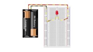
A breadboard works perfectly for testing. You push wires into holes to check your logic. Once you confirm the layout works, those loose wires become a liability. A slight bump disconnects the battery. A circuit board fixes this problem entirely. The factory etches flat copper lines directly onto a rigid surface. These flat lines, called traces, act exactly like your jumper wires. They carry the electrical current from the battery to your LED without shifting or breaking.
Reading a reliable printed circuit board guide shows you how these thin copper lines handle the exact same voltage and current as a thick plastic-coated wire. You gain a compact, permanent way to route power across your desk.
The Layers of a Standard Board
A finished board looks like a single piece of plastic. It actually contains multiple compressed layers. Recognizing these layers helps you troubleshoot problems when parts fail to turn on.
| Layer | Material | Function |
| Base | Fiberglass | Gives the board its rigid physical strength |
| Traces | Copper | Conducts electricity between the components |
| Soldermask | Polymer layer | Protects the copper from short circuits and corrosion |
| Silkscreen | Ink | Prints the labels and outlines for easy assembly |
The soldermask gives the board its famous green color. This coating prevents hot solder from flowing across the copper and creating accidental connections. It forces you to connect your parts only at specific exposed silver pads.
Moving From Breadboards to Permanent Projects
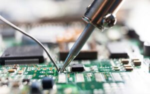
Transitioning to a permanent project requires a new tool. You trade your bare hands for a soldering iron. Soldering melts a soft metal alloy, fusing the component legs directly to the exposed copper pads on the board. This creates a mechanical bond and a permanent electrical path.
Learning this physical skill connects directly to the tech basics and concepts you practiced earlier. A soldered joint simply replaces the friction of a breadboard clip. The rule of the closed loop remains exactly the same. The electricity must still leave the battery, travel through the trace, enter the component, and return to ground.
Reading the Map Before You Build
A bare board looks intimidating before you add the parts. The white text printed on the top layer acts as your instruction manual. This silkscreen layer tells you exactly where every resistor and microchip belongs.
You match the component shapes to the printed outlines. A circle with a flat edge shows you exactly how to orient an LED to maintain the correct polarity. A small plus sign marks the positive battery terminal. Studying a circuit board labeling tutorial trains your eyes to read these symbols like a roadmap. You verify every label before applying the hot iron.
Taking the time to read the board prevents reversed parts and damaged hardware. Your early builds become much more reliable when you rely on the printed map instead of guessing.