An introduction to using a microcontroller marks the exact moment your electronics journey shifts from building simple reactions to designing smart behaviors. When you first start learning electronics, you rely on physical components to make decisions. A switch completes a circuit, or a sensor triggers a direct voltage change. But as your projects grow, you eventually want your circuits to wait, count, make complex choices, or respond differently based on specific conditions. To do that without building massive, complicated wiring webs, you need a programmable brain.
A microcontroller is essentially a tiny, self-contained computer placed on a single microchip. It does not have a keyboard, a screen, or massive hard drives like a desktop computer, but it contains everything it needs to read electrical signals, process those signals using code you write, and send out new electrical commands in response. For robotics enthusiasts and beginner builders alike, understanding this component is the key to unlocking automation.
Why A Microcontroller Is The Next Logical Step
In basic electronics, a circuit’s behavior is entirely determined by how the parts are physically connected. If you wire a basic buzzer alarm circuit, the buzzer will sound the exact moment the switch is closed. But what if you want the alarm to wait ten seconds before sounding? What if you want it to flash an LED three times first, or only trigger if it is also dark in the room?
Accomplishing that with raw hardware requires complex timing chips and logic gates. A microcontroller solves this by moving the logic from the physical breadboard into software. You wire the switch to an input pin and the buzzer to an output pin, and then you write a few lines of code to tell the board exactly how to manage the interaction. This makes your physical wiring much cleaner and allows you to completely change how your project behaves just by uploading a new script.
What A Microcontroller Actually Does
At a practical level, a microcontroller performs a continuous loop of three basic tasks: reading inputs, processing logic, and driving outputs. The physical connections on the board, known as Input/Output (I/O) pins, act as the bridge between the digital brain and the physical world.
When you connect a simple analog temperature sensor to an input pin, the microcontroller converts that physical voltage into a digital number. Its internal processing unit then checks that number against the rules you wrote in your code. If the number crosses your defined threshold, the microcontroller sends a voltage out through a different pin to spin a cooling fan or light a warning LED. It is a constant, high-speed cycle of reading the environment and reacting to it.
Common Microcontroller Boards For Beginners
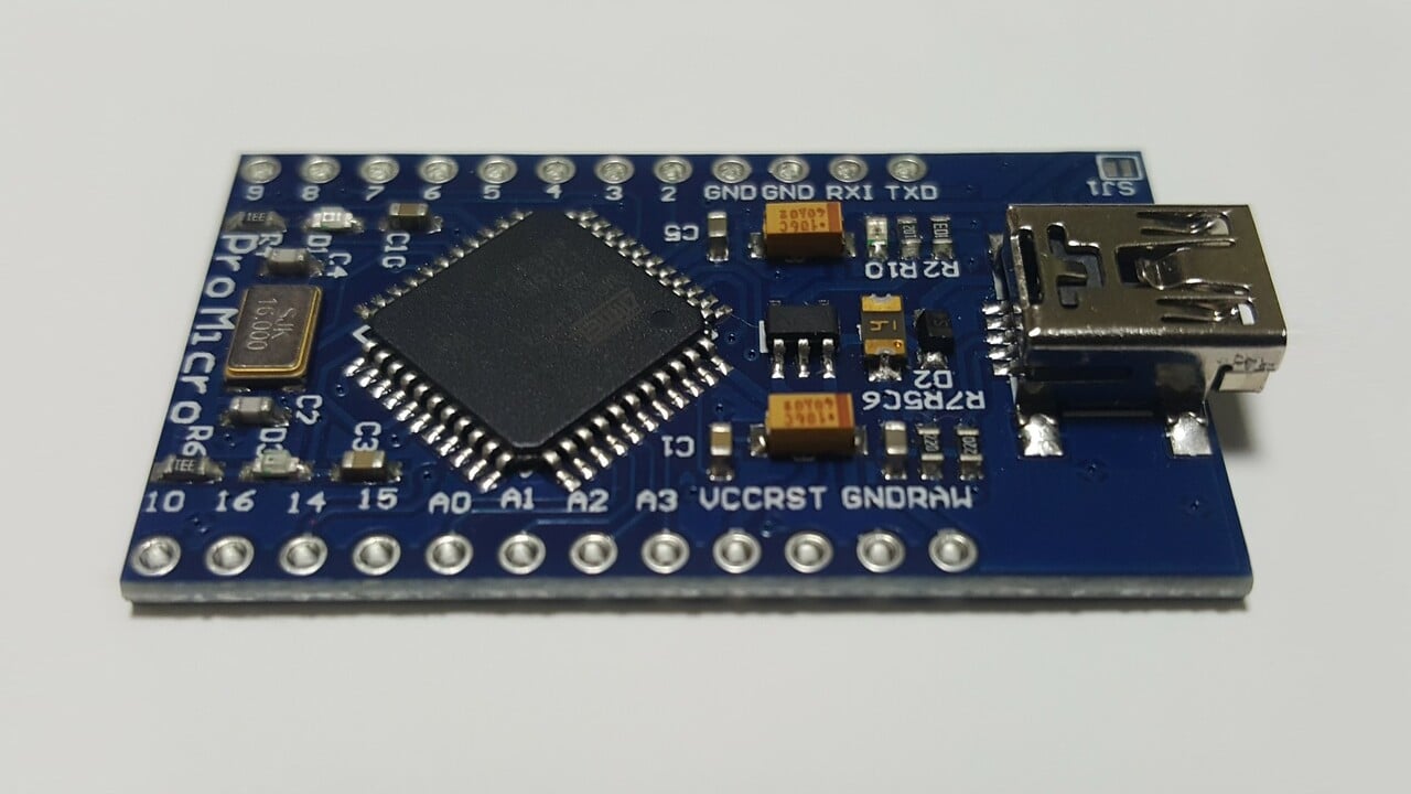
When you are ready to start programming, you rarely buy a bare microcontroller chip. Instead, you buy a development board, which includes the chip, a USB connection for your computer, and easy-to-use pin headers for your breadboard jumpers.
| Board Type | Primary Programming Logic | Best Beginner Benefit |
| Arduino Uno | C++ based Arduino language | Massive community support and the industry standard for learning hardware |
| Raspberry Pi Pico | MicroPython or C/C++ | Excellent for learning modern coding alongside physical hardware |
| micro:bit | Block-based coding or Python | Ideal for kids and absolute beginners needing visual programming |
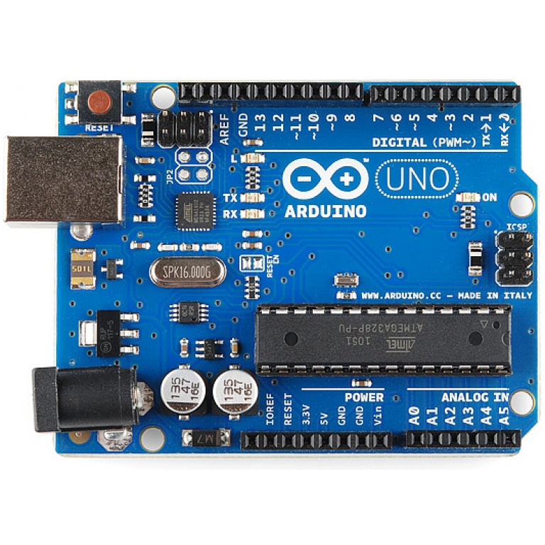
Choosing the right starting point depends on your comfort level with code. The official Arduino getting started guide is a highly recommended read for understanding how standard C++ logic interacts with physical pins, as it provides a robust foundation for nearly all modern DIY robotics.
How Microcontrollers Change Circuit Design
Introducing a microcontroller changes how you approach a breadboard. You are no longer building a single, continuous power path from a battery through a sensor to a load. Instead, you are building two separate halves of a system. The input side talks to the microcontroller, and the output side listens to it.
This separation means your wiring becomes incredibly modular. If you decide to upgrade a simple motion detector project by adding a programmable board, the sensor wiring and the output wiring remain largely independent of each other. The microcontroller sits in the middle, acting as the traffic director. This modular approach is exactly how complex robotics systems are designed, breaking massive machines down into manageable, programmable sub-systems.
Common Problems When Moving To Programmable Boards
The biggest hurdle beginners face when transitioning to microcontrollers is the introduction of a new failure point: the code. In purely physical electronics, a circuit that fails to work usually has a reversed polarity, a dead battery, or a loose jumper wire. With a microcontroller, your wiring might be flawless, but a single missing semicolon in your code will stop the entire system from functioning.
Troubleshooting now requires checking both domains. If an LED fails to blink, you must ask if the LED is plugged in backward, or if the code is sending the signal to the wrong digital pin. The best habit to develop early is testing your hardware separately from your software. Always ensure an output component works with direct power before assuming your code is broken.
Safe Testing With Digital Logic
Working with microcontrollers usually means stepping down to lower voltages, typically 5V or 3.3V logic. While this is incredibly safe from a personal shock perspective, digital boards are highly sensitive to electrical mistakes.
Applying too much voltage to an input pin or trying to draw too much current directly from an output pin can permanently damage the microcontroller chip. Always use current-limiting resistors with your LEDs, and never try to power motors directly from the board’s I/O pins. Understanding how to use external power safely alongside digital signals is a critical habit that protects your hardware and keeps your learning journey moving forward.