Building an electronics project is only the first half of the learning process. The second half, and often the most valuable part, happens when the circuit does not work on the first try. Knowing how to troubleshoot a circuit step by step transforms a frustrating moment into a clear, logical problem-solving exercise. Instead of randomly moving wires and hoping for a better result, you learn to read the physical clues your project is giving you.
For beginners, a non-working circuit rarely means you lack the skills to build it. It usually means a single, small detail was overlooked. Stamps in Class projects are designed to be built on breadboards, which makes them incredibly easy to adjust, but also easy to miswire. Approaching these mistakes with a calm, analytical mindset is the exact same method professional engineers use when designing complex hardware.
Start With the Power Source
When a circuit fails to turn on, the most common culprit is the power source. Before you check any complicated sensors or microcontrollers, you must verify that electricity is actually reaching the breadboard. If your project uses a battery pack, check that the batteries are fresh and properly seated in their holder. A surprising number of beginner projects fail simply because a battery was inserted backward.
Next, trace the path from the power source to the breadboard rails. Ensure the positive wire is connected to the red power rail and the ground wire is connected to the blue or black ground rail. If your project requires bridging power from one side of the breadboard to the other, verify that those tiny jumper wires are securely pushed into place. If power is not moving down the rail, none of the components connected to it will function.

Inspect Your Breadboard Connections
Breadboards are fantastic for learning, but they rely on friction to hold wires in place. A loose jumper wire can break a circuit path instantly. Gently press down on every wire and component leg to ensure they are fully seated inside the breadboard clips. If a wire feels unusually loose, move it to an adjacent hole in the same row to establish a firmer connection.
You must also check for accidental short circuits. This happens when two bare wires touch each other, or when the exposed metal legs of components like resistors lean across the board and make contact. Keeping your wiring neat and clipping your component legs to an appropriate length goes a long way in preventing these hidden connections. Clean layout makes tracing the flow of electricity much easier.
Verify Component Placement and Polarity
Many electronic parts only allow electricity to flow in one direction. This property is known as polarity. If a polarized component is placed backward, the circuit will not work, and the component might even be damaged. Light Emitting Diodes (LEDs) are the classic example. The longer leg of an LED must connect to the positive side of the circuit, while the shorter leg connects to ground.
Electrolytic capacitors, buzzers, and microchips also require specific orientations. Always double-check your project diagram against your physical board. If an LED is not lighting up, pulling it out, flipping it around, and plugging it back in is a quick and safe diagnostic test.
A Practical Troubleshooting Example
To make the process easier to follow, here is a quick reference table showing common beginner problems and the logical first step to fix them.
| Symptom | Likely Cause | First Troubleshooting Step |
| Nothing turns on at all | Power supply issue | Check batteries and main power rail jumpers |
| LED is completely dark | Reversed polarity | Flip the LED to ensure the long leg faces positive |
| LED turns on but is very dim | Incorrect resistance | Check the resistor color bands to ensure the value is not too high |
| Component gets noticeably hot | Short circuit or excess current | Disconnect power immediately and check for touching wires |
Use Logic Before Moving Wires
When physical inspections do not reveal the problem, you need to rely on the electrical rules you have learned. This is where understanding Ohm’s Law becomes an incredibly powerful troubleshooting tool. If you know the voltage of your battery and the resistance in your circuit, you already know how the circuit is supposed to behave.
If your math tells you an LED should be bright but it appears dim, you can confidently assume the resistor you grabbed is the wrong value. Using theoretical knowledge to check your physical build stops you from making random guesses. It forces you to compare what is actually happening on the board against what the rules of electronics say should be happening.
Safe Testing Habits for Beginners
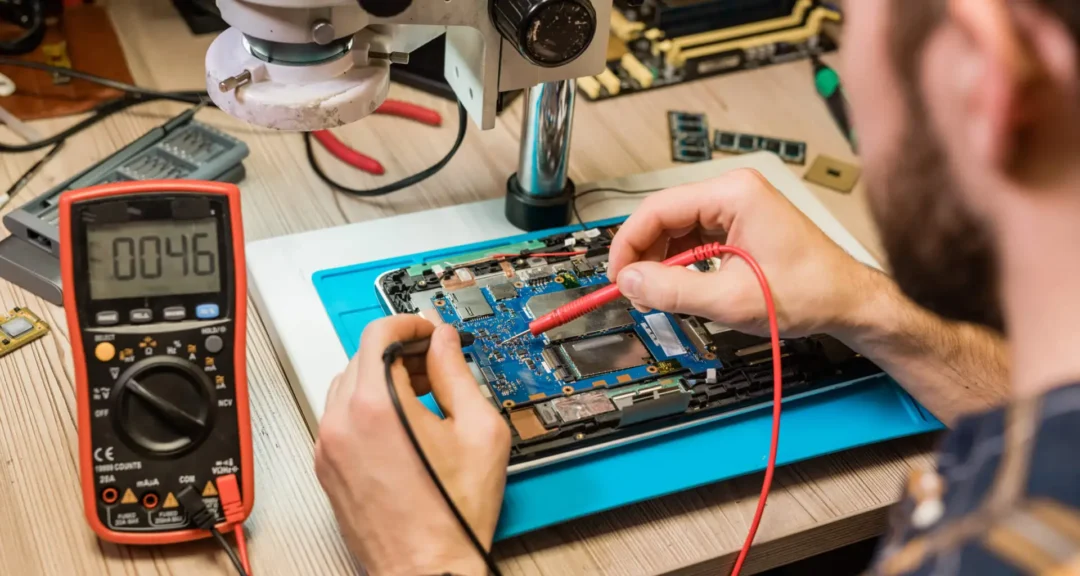
As your projects grow beyond simple light and sound circuits, visual inspections will only take you so far. You will eventually need a way to “see” the electricity. A digital multimeter is the standard tool for this job. It allows you to measure exactly how much voltage is arriving at a specific pin or check if a wire has a hidden break inside its insulation.
For those ready to take this next step, reading a guide on how to use a multimeter will dramatically speed up your diagnostic process. Always remember to test safely. Even with low-voltage beginner kits, you should never alter wiring while the power is connected. Unplug the battery, make your adjustment, and then plug it back in to observe the result.
Final Thoughts
Learning how to troubleshoot a circuit step by step is an essential milestone in your electronics journey. Every time a circuit fails, it provides an opportunity to deepen your understanding of how electricity flows and how components interact. By systematically checking your power, connections, and polarities, you build confidence in your ability to solve technical problems. Embrace the troubleshooting process, because it is the exact skill that separates someone who simply follows instructions from a true electronics builder.