Ground in electronics is the reference point that helps a circuit make sense. In most beginner projects, ground is the point labeled 0 volts, and every other voltage in the circuit is measured relative to it. That does not always mean it is literally connected to the earth. In many low-voltage electronics builds, ground is simply the shared return path and common reference that lets current flow in a complete loop.
For beginners, this idea matters because circuits stop being confusing once you realize that voltage is always measured between two points. A battery may be 9 volts, but that only means one side is 9 volts higher than the chosen reference point. When your diagram shows a GND symbol, it is telling you where that reference point lives in the circuit. That is why ground appears in schematics, breadboard builds, sensors, buzzers, LEDs, and microcontroller projects across Stamps in Class.
Ground in Electronics Is the Shared Reference Point
A simple way to think about ground is as the home base for voltage measurements. If a point in a circuit is 5V, that usually means it is 5 volts above ground. If another point is 0V, that means it is at the same electrical potential as ground. Without that shared reference, voltage numbers would not mean much because there would be no agreed starting point for comparison.
This is why ground is so common in beginner schematics. It reduces clutter and makes the circuit easier to read. Instead of drawing a long wire back to the negative side of the power source every time, a designer can use the ground symbol to show that several points are electrically connected to the same reference. That makes diagrams cleaner and easier to follow when you are first learning how a circuit works.
Why Ground Matters in Every Circuit
Ground matters because a circuit only works when current has a complete path. In many beginner electronics projects, current leaves the positive side of the power source, passes through components like LEDs, resistors, or buzzers, and returns through ground to the negative side of the source. If that return path is missing, the circuit is open and the device will not behave the way you expect.
That is why so many troubleshooting problems come back to ground connections. A loose signal wire can cause problems, but a missing ground often prevents the entire circuit from working. Sensors can give unstable readings, buzzers may stay silent, and LEDs may not light at all if the components do not share the same ground reference. In practical terms, ground is what helps all the parts of the circuit “agree” on where zero volts is.
Ground Is Not Always Earth Ground
One of the most common beginner misunderstandings is thinking that ground always means the physical earth. In household wiring and some electrical systems, earth ground is a real safety connection to the ground outside. In low-voltage electronics, though, ground is often just the circuit’s chosen reference point and return path. Those two ideas are related, but they are not identical.
That distinction matters because beginner electronics kits, breadboards, batteries, and classroom microcontroller projects usually use circuit ground, not earth ground. When a schematic shows GND on a breadboard project, it usually means “connect this to the common reference line” rather than “connect this to a grounding rod in the soil.” Understanding that difference helps beginners read schematics more confidently and avoid unnecessary confusion.
How Ground Works on a Breadboard
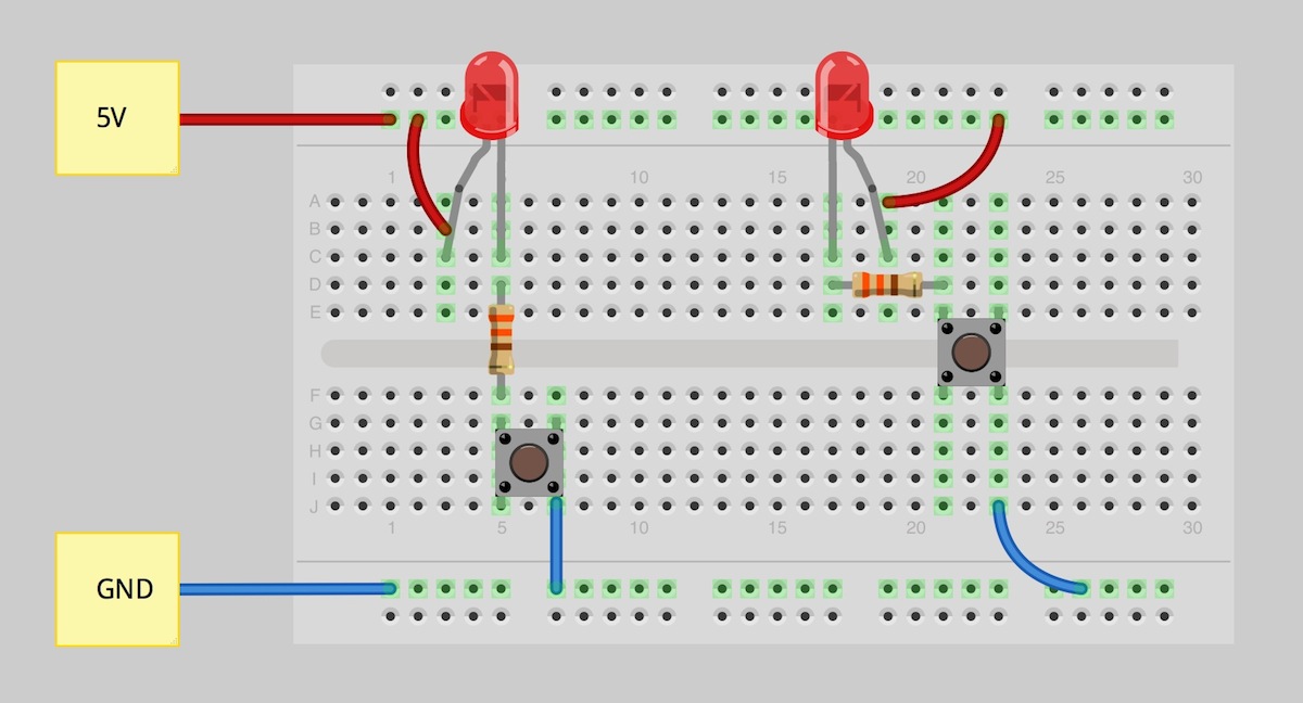
On a breadboard, ground is often connected along one of the side rails so multiple parts can share the same return path. That makes it easier to wire simple builds because components do not each need their own direct wire back to the battery or board ground pin. Once the ground rail is connected properly, you can plug several parts into that common line and keep the circuit organized.
This is one reason breadboards are so useful for learning. They help beginners see that a circuit is not just a collection of isolated parts. It is a connected system where voltage, current, and reference points all work together. When a build seems random or messy, checking whether the ground rail is actually connected is often one of the first smart troubleshooting steps.
Ground in Simple Beginner Projects
In an LED circuit, the ground connection gives current a way back to the power source after passing through the resistor and LED. In a buzzer project, the buzzer may only sound correctly when the ground path is complete. In a sensor build, both the sensor and controller usually need a common ground so the signals can be interpreted properly. That is why ground shows up in almost every beginner project, even when the project itself seems simple.
Ground also becomes more important as projects include more than one module. A microcontroller board, a sensor, and an output device may all use separate wires for power and signals, but they often still need a shared ground to communicate reliably. Without that shared reference, measured voltages can become inconsistent and the project may act unpredictable even if the wiring looks almost correct.
A Quick Ground Reference Table
| Ground Type | What It Means | Where Beginners Usually See It |
|---|---|---|
| Circuit Ground | The common 0V reference point in a circuit | Breadboards, LEDs, sensors, buzzers |
| Common Ground | A shared reference used by multiple connected parts | Microcontrollers and modules |
| Earth Ground | A safety connection tied to the earth | Building wiring, power systems |
| Chassis Ground | A conductive enclosure used as a reference or shield | Some equipment and enclosures |
This table helps show why the word “ground” can seem confusing at first. In beginner electronics, the most common version is usually circuit ground or common ground, not earth ground. That is the version students use most when building hands-on projects in class or on a breadboard.
Common Mistakes Beginners Make With Ground
A common mistake is assuming that connecting the positive side of a circuit is enough to make it work. In reality, the current needs a full loop, and ground is often part of that loop. Another mistake is forgetting that two connected devices may need a shared ground even if both have power. That issue appears often when beginners add a sensor or module to a microcontroller project and the signal seems wrong or unstable.
Another misunderstanding is treating every ground symbol as if it means the same thing in every context. In schematics, ground usually marks a reference node, but in larger systems there can also be analog ground, digital ground, chassis ground, and earth ground. Beginners do not need to master every advanced detail right away, but they do need to understand that ground is a practical reference point, not just a mysterious symbol on the page.
Why Ground Helps You Troubleshoot Faster
Once you understand ground, troubleshooting becomes much more logical. If a circuit does not power up, one of the first things to check is whether the device actually has a return path to ground. If a sensor reading looks inconsistent, you can check whether the sensor and controller share the same reference point. That approach saves time because it moves you away from guessing and toward checking the circuit in a structured way.
That is also why learning how power flows is such a useful next step for beginners. Once you see ground as part of a complete electrical path instead of just a symbol, schematic reading and breadboard building both become easier. The circuit starts to feel less like a puzzle and more like a system you can understand.
Final Thoughts
Ground in electronics is the shared reference point that gives voltage meaning and helps current return through a complete circuit. It matters because nearly every beginner project depends on that reference to work correctly, whether you are wiring an LED, using a buzzer, or connecting a sensor to a microcontroller. Once beginners understand ground, they read schematics faster, troubleshoot better, and build circuits with more confidence.
For a deeper beginner-friendly foundation, it also helps to review Stamps in Class content on how power flows and compare it with a broader external explanation like All About Circuits’ guide to ground.