Computers love predictability. They excel at following exact instructions repeatedly without variation. Forcing a highly structured microchip to act unpredictably requires a specific hardware approach. When you build an Arduino randomizer project, you train your microcontroller to simulate chance. People use these circuits as digital dice for board games or to generate arbitrary results for testing. Just as sports fans might check today’s betting odds to analyze unpredictable matchups, hardware builders rely on randomizer circuits to introduce true variation into their code.
Wiring the Hardware Components
You need a physical way to display the final result. Six LEDs serve as the perfect output for a standard digital dice roller. You arrange these LEDs in a straight row on your breadboard, connecting each positive leg to a separate digital pin on the development board. You wire a 220-ohm resistor to each negative leg, bridging them to the common ground rail. This standard setup mirrors many of the hands-on kits and builds you already practice on your desk.
Next, you add a momentary pushbutton to trigger the roll. You connect one side of the button directly to ground and the other side to a digital input pin. Using the internal pull-up resistor of the microcontroller keeps the wiring extremely clean. Reading a reliable pull-up resistors tutorial shows you how this internal feature prevents the input pin from picking up false static signals from the surrounding room.
Solving the Predictable Math Problem
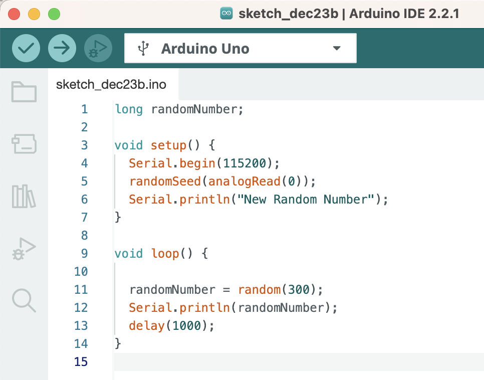
Microcontrollers struggle to generate truly random numbers natively. A basic math function forces the board to pick the exact same sequence of numbers every time you turn the power on. The chip uses a fixed formula based on its internal clock, causing this frustrating repetition. You must feed the chip unpredictable data from the physical environment to fix this logic flaw.
You leave one analog pin completely disconnected on your board. This empty pin acts as a tiny antenna, reading stray electromagnetic noise from the lights and wires in your room. You tell the code to read this fluctuating noise and use it as the starting seed for the math formula. Studying an official Arduino random function guide explains how the software command grabs this environmental static and forces the microchip to produce a unique sequence every single time you apply power.
| Component | Circuit Function | Connection Point |
| LED Array | Displays the final random result | Digital Output Pins 2-7 |
| Pushbutton | Triggers the calculation | Digital Input Pin 8 |
| Empty Analog Pin | Reads environmental noise | Analog Input A0 |
| Current Resistors | Protects LEDs from burning out | Ground Rail |
Writing the Selection Code
Your software loop waits patiently for a button press. Once the input pin detects the connection to ground, the code triggers the math function. You set the logic function to pick a number between one and six. A series of conditional statements reads that generated number and turns on the corresponding LED. If the chip picks a three, it sends high voltage to the third LED in your breadboard row.
You create visual suspense by adding a quick animation before the final result appears. The code rapidly flashes all the LEDs in sequence, slowing down gradually to mimic a rolling die losing momentum. This delay logic requires precise timing. You structure the loop so the animation pauses the main program just long enough to look realistic without freezing the board entirely.
Preventing Button Bounce Errors
Physical buttons contain small metal plates that smash together when you press down. These plates vibrate microscopically, causing the electrical signal to bounce rapidly between high and low states. The fast-acting microcontroller reads this vibration as dozens of separate button presses in a fraction of a second, causing the randomizer circuit to trigger repeatedly and ruin the suspense.
You filter out this mechanical noise using software. You instruct the code to ignore any extra signals that happen within fifty milliseconds of the first press. Reviewing proven hardware debouncing techniques teaches you how to implement this simple timing filter. This guarantees your circuit registers exactly one clean press every time your finger hits the plastic switch, giving you a perfect, single random result on demand.