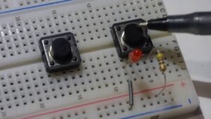
Subject: Simple Circuit Diagram
Duration: 45–60 minutes
Prerequisites: None
Level: Beginner
Learning Objectives
By the end of this lesson, students will be able to:
- Identify basic electronic symbols (battery, resistor, LED, switch, ground)
- Understand how components connect in a simple circuit diagram
- Trace the flow of electricity in a simple circuit
- Match a basic schematic to a real-world breadboard circuit
Why Circuit Diagrams Matter
Circuit diagrams (also called schematics) are like maps. Instead of showing what components look like, they show how components are connected.
Engineers and hobbyists use diagrams to:
- Plan circuits
- Troubleshoot problems
- Share designs with others
Understanding schematics is the first step toward building your own electronics projects.
The Most Common Beginner Symbols
Battery


What it means: Provides power (voltage)
Key detail: Long line = positive (+), short line = negative (–)
LED (Light Emitting Diode)

What it means: A light that only allows current to flow in one direction
Key detail: The arrow direction shows current flow
Resistors

What it means: Limits current
Why important: Protects components like LEDs from burning out
Switch
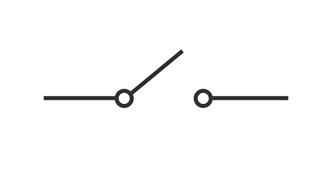
What it means: Opens or closes the circuit
Open switch: No current flows
Closed switch: Current flows
Ground

What it means: Common return path for current
Tip: Not always literally the earth — often just the negative side of power
Understanding Lines and Connections
In a schematic:
- Lines = wires
- Dots at intersections = connected
- Crossing lines without a dot = NOT connected
Think of it like roads:
- If there’s an intersection dot → roads connect.
- No dot → one road just passes over another.
Reading a Simple Circuit Step-by-Step
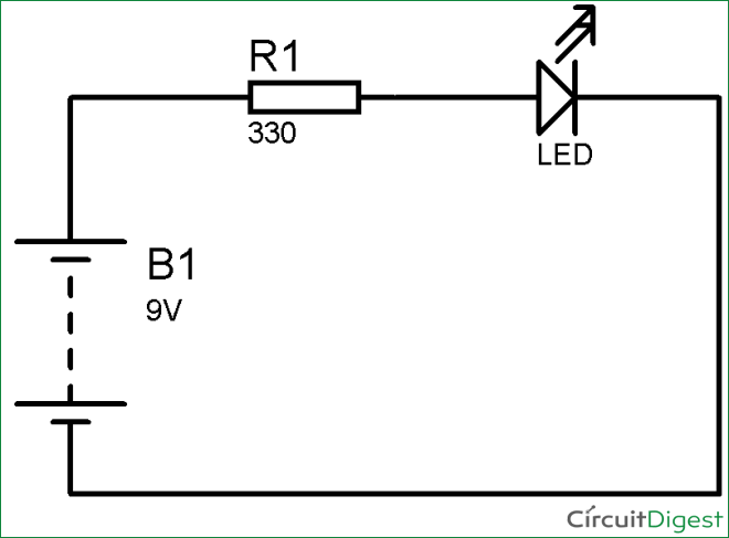
Let’s look at a basic LED circuit.
Step 1: Find the Power Source
Start at the battery.
Step 2: Follow the Path
Trace from positive → through the resistor → through the LED → back to negative.
Step 3: Identify Component Roles
- Switch controls power
- Resistor limits current
- LED lights up
Series vs Parallel (Beginner Introduction)
Series Circuit
Components are connected one after another in a single path.
Clue in diagram: Only one path for current.
Parallel Circuit
Components branch off into multiple paths.
Clue in diagram: You see splits in the wiring.
(For beginners, start with series circuits first.)
5️⃣ Hands-On Activity (15–20 Minutes)
Activity: Build What You Read
Materials Needed:
- Breadboard
- 9V battery (or 3V coin cell)
- 220Ω resistor
- LED
- Small switch
- Jumper wires
Task:
- Draw the schematic of the LED circuit.
- Build it on a breadboard.
- Compare the schematic to the physical layout.
- Turn the switch on and off.
Discussion Questions:
- What happens if you remove the resistor?
- What happens if you flip the LED backwards?
- What happens if the switch is open?
Common Beginner Mistakes
❌ Thinking diagrams show physical layout
❌ Ignoring polarity (+ and –)
❌ Missing connection dots
❌ Forgetting resistors for LEDs
Quick Assessment (Exit Ticket)
- What does a resistor do?
- How can you tell if wires connect at a crossing?
- In what direction does current flow in a simple DC circuit?
- What happens if a switch is open?
Extension Challenge
- Draw a schematic with two LEDs in series
- Draw a schematic with two LEDs in parallel
- Add a second switch
- Label all parts
Instructor Notes
Keep it visual.
Beginners learn better when they see symbols repeatedly next to explanations.
Encourage tracing with a pencil.
Have students physically trace the path of current.
Relate to real life.
Compare circuit diagrams to:
- Subway maps
- Road maps
- Blueprints
Key Takeaways
- Schematics show connections, not physical placement
- Each symbol represents a real component
- Lines = wires
- Dots = connections
- You always start reading from the power source