Switches and buttons are the simplest way to let a person control an electronic circuit. Flip a switch and a light turns on. Press a button and a buzzer chirps. Under the hood, what’s really happening is straightforward: you’re opening or closing a path for electricity—and that single change can act like a “yes/no” signal to the rest of a circuit.
In this guide, you’ll learn the most common switch and button types, how they work electrically, how to wire them on a breadboard, and the #1 beginner problem you’ll run into (and how to fix it).
Breadboard 101: how to place parts on a breadboard
LED Projects: simple LED projects to practice wiring
What a Switch Really Does
In electronics, a switch is a component that either:
- Connects two points in a circuit (closed switch = current can flow), or
- Disconnects them (open switch = current cannot flow)
That’s it. But this tiny on/off control is powerful because circuits can interpret it as:
- “Turn power on/off”
- “Start/stop a device”
- “Send an input signal to a microcontroller”
- “Select between modes”
Switch vs Button: What’s the Difference?
Both control a circuit, but they behave differently:
Switch (stays where you put it)
A typical toggle switch is latching:
- Flip ON → it stays ON
- Flip OFF → it stays OFF
Button (only works while you press it)
Most pushbuttons are momentary:
- Press → circuit connects
- Release → circuit disconnects
If you’ve ever used a doorbell, that’s a classic momentary button: it only sends a signal while you’re pushing.
Common Types of Switches and Buttons
Here are the ones you’ll see most in beginner builds:
1) SPST Switch (Single Pole, Single Throw)
- The simplest: one input, one output
- It’s basically an ON/OFF gate
Use it for: turning LEDs, motors, or whole projects on/off
2) SPDT Switch (Single Pole, Double Throw)
- One input connects to one of two outputs
- It “selects” between two paths
Use it for: choosing modes, selecting between two LEDs, direction switches (in some designs)
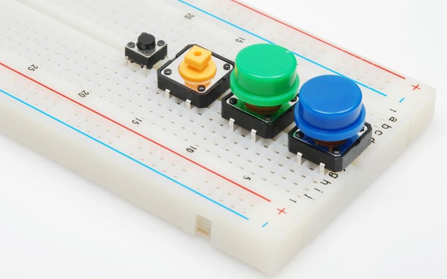
3) Tactile Pushbutton (Momentary)
- The little “clicky” button used on breadboards
- Usually normally open (NO): not connected until you press
Use it for: input signals, reset buttons, simple games
4) Slide Switch
- A small switch that slides left/right
- Often SPDT style
Use it for: compact projects, on/off power, mode select
Normally Open vs Normally Closed (NO vs NC)
Switches and buttons are often described by what they do when you’re not touching them.
- Normally Open (NO): open at rest → press/flip to connect
- Normally Closed (NC): connected at rest → press/flip to disconnect
Most beginner pushbuttons are NO, which is usually what you want for “press to do something.”
Wiring a Button on a Breadboard (The Right Way)
A classic beginner build is: press button → LED turns on.
But there’s a trap: many 4-pin tactile buttons have internal connections that confuse people.
The 4-pin button trick
On most tactile buttons:
- Two pins on one side are connected together
- Two pins on the other side are connected together
- Pressing the button connects both sides
Important: The button should straddle the middle gap of your breadboard so each “side” lands on different rows.
The #1 Problem: Floating Inputs
If you’re using a button as a signal input (especially with Arduino or other microcontrollers), you can run into a weird issue:
- You press the button and it works…
- But when you’re not pressing it, the input randomly flips HIGH/LOW
That’s because the input pin is floating—it isn’t firmly tied to HIGH or LOW.
Fix: Use a Pull-Down or Pull-Up Resistor
A pull-down resistor gently ties the signal line to ground so it reads LOW when not pressed.
Example idea:
- Button connects signal to +5V when pressed (HIGH)
- Pull-down resistor connects signal to GND when not pressed (LOW)
A pull-up resistor does the opposite:
- Signal reads HIGH by default
- Button connects it to ground when pressed
Good news: Many boards have built-in pull-up resistors you can enable in code, but it’s still important to understand what’s happening.
Switch Bounce: Why One Press Can Look Like Many
Buttons aren’t perfect. When you press one, the metal contacts can “bounce” for a few milliseconds, making the circuit connect/disconnect quickly:
- Your circuit thinks you pressed 5 times
- You swear you pressed once
This is called switch bounce.
How beginners handle bounce
- For simple LED circuits: ignore it (you won’t notice)
- For microcontrollers: use a short delay or “debounce” logic
Project: Button-Controlled LED (Beginner Build)
If you want a quick hands-on build:
Goal: Press button → LED turns on
You’ll need:
- Breadboard + jumper wires
- LED
- 220Ω–330Ω resistor (LED current limiter)
- Momentary pushbutton
Simple approach:
- Put the LED in series with a resistor
- Put the button in series so it completes the circuit only when pressed
Once that works, level up by moving the button to a signal input on a microcontroller and learning pull-ups/pull-downs.
Where Switches and Buttons Show Up in Real Electronics
Once you start looking, you’ll see switches everywhere:
- Power buttons on devices
- Keyboard keys (each key is basically a switch)
- Door sensors (often NC switches)
- Limit switches in robotics (detect movement end points)
- Game controllers, remote controls, and toys
In other words: learning switches is learning how real-world “human input” becomes an electrical signal.
Quick Troubleshooting Checklist
If your switch/button circuit isn’t working, check these:
- Is the button straddling the breadboard gap?
- Are you accidentally using two pins on the same connected side of the button?
- Is your LED facing the right direction? (long leg = positive/anode)
- Did you include an LED resistor (220Ω–330Ω)?
- If using a microcontroller input: do you have a pull-up or pull-down?
Conclusion
Switches and buttons are the gateway to interactive electronics. They turn circuits from “always on” into “reacts to you.” Once you understand open vs closed, NO vs NC, and how to avoid floating inputs, you can build everything from simple LED controls to real input systems for robots, games, and sensors.
If you’re building along at home, start with a button-controlled LED, then try a toggle switch for power control—and you’ll quickly see how user input works in circuits.