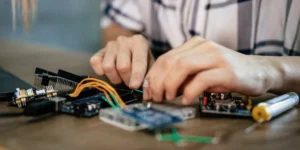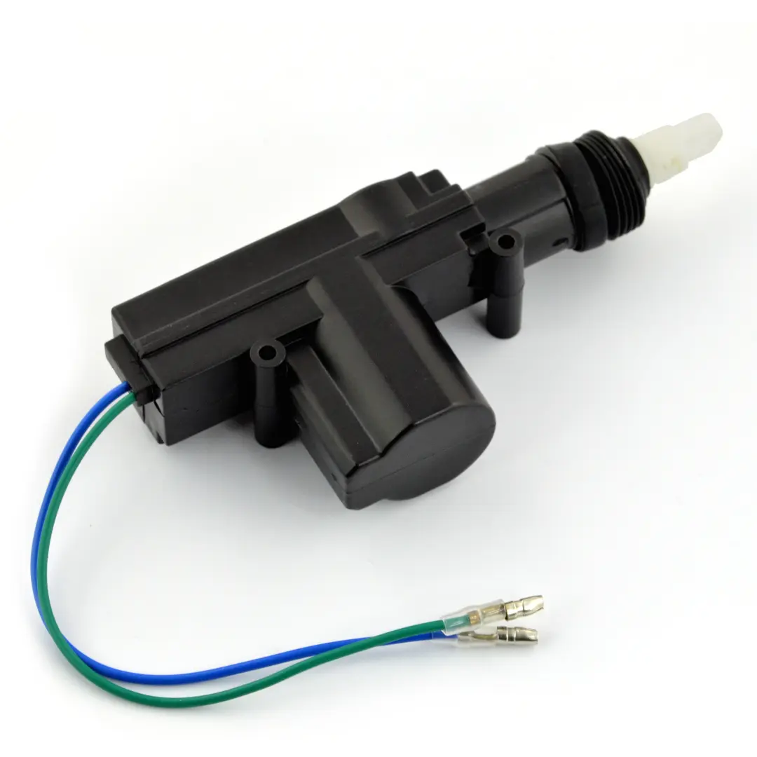
Teaching electronics starts by making invisible concepts visible. A strong actuator lesson plan bridges the gap between raw voltage and physical action. You show learners exactly how an electrical signal leaves a microcontroller and does real work on the desk. You stop talking about abstract current flow and start making things move, light up, and make noise.
Moving From Sensing to Doing
Most early learning focuses on inputs. You wire a switch or read a temperature sensor. Actuators form the second half of that conversation. They represent the output. If a sensor reads the environment, an actuator changes the environment. You press a button, and a physical mechanism reacts. This direct cause and effect builds immediate confidence for first-time builders.
Structuring your beginner electronics lesson plans around this input-to-output loop creates a clear logical path. A student learns to trigger a motor only after they know how to read the button press.
Comparing Standard Output Components
You need to select the right components for your class. Giving students heavy industrial parts leads to blown fuses and frustration. Breadboard-friendly parts keep the learning focused and safe.
| Actuator Type | Physical Output | Typical Use Case |
| LED | Visible light | Status indicators and simple visual feedback |
| Piezo Buzzer | Sound waves | Audible alarms and basic notifications |
| Servo Motor | Controlled rotation | Sweeping arms and steering mechanisms |
| DC Motor | Continuous spinning | Driving wheels on small robotic chassis |
Reviewing a reliable motor selection guide helps you pick the exact right hardware for the age and skill level of your students. Small servos work best for precise logic tests, and standard DC motors fit perfectly into moving chassis builds.
Managing Voltage and Current Spikes
Moving parts require more energy than simple lights. An LED runs happily on a few milliamps from a tiny battery. A motor demands a massive rush of current the moment it starts spinning. If a student wires a motor directly to a small microcontroller pin, the resulting power spike often resets the board or damages the chip permanently.
Teaching students to isolate power supplies fixes this problem. You separate the fragile logic brain from the heavy-lifting motors. You route the high-current battery pack through a motor driver board. Reading clear motor control fundamentals gives you the exact wiring diagrams needed to keep your classroom hardware safe during these high-power experiments.
Testing the Build Incrementally
Students rush to turn everything on at once. A broken wire or reversed polarity immediately halts the entire project. You must enforce incremental testing. You tell the class to wire the power rails first. Next, they connect the control signal. Finally, they add the physical actuator.
Testing each stage separately pinpoints errors fast. If a servo motor refuses to sweep, the student checks the code logic with an LED before assuming the motor itself failed. Breaking the problem down makes hands-on kits and builds feel like an achievable puzzle rather than a frustrating chore. This structured testing process turns your students from simple diagram followers into independent problem solvers.
Connecting Code to Physical Motion
Writing software for an actuator requires precision. You teach the class how digital signals send instructions to the hardware. A microcontroller sends a quick pulse of electricity to a servo. The length of that pulse tells the motor exactly what angle to hold. If the code sends a long pulse, the arm swings wide. A short pulse snaps it back to the center.
You show students the raw numbers on their screens. Changing a variable from zero to ninety results in a direct ninety-degree rotation on their desk. Seeing their typed code produce real physical motion cements the lesson entirely.