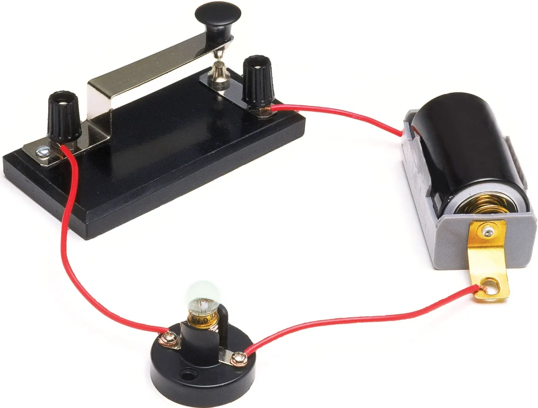
Electronics often look complicated from the outside. Wires cross over each other, lights flash, and sensors react to the room. Complex Circuits can be broken down into simple concepts. A circuit is just a closed loop. Electricity leaves a power source, travels through a path, does some work, and returns to the source. Grasping how power flows in simple electronics projects changes the way you look at a breadboard. You stop seeing a jumble of parts and start seeing a clear path.
The Complete Loop Requirement
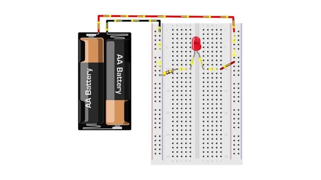
Electricity refuses to move without a guaranteed way back home. If you attach a wire to the positive side of a battery and run it to an LED, nothing happens. The electrons need a return path to the negative side, often called ground. This physical requirement dictates every connection you make on your desk. A broken wire, a loose pin, or an unplugged component stops the flow instantly.
Visualizing this invisible force helps you build better projects. Think of voltage as the pressure pushing the electricity, and current as the actual volume of electricity moving through the wire. When you block that path, the pressure builds up but the current stops. Reviewing a visual electricity basics tutorial makes this relationship clear. The moment you close the loop, the pressure pushes the current through your components.
Reading the Components on Your Breadboard
Components use the electricity as it passes through the loop. An LED takes that electrical energy and turns it into light. A motor turns it into kinetic motion. As the electricity does this work, it loses pressure. By the time the current returns to the ground side of your battery, the voltage drops to zero.
Placing parts in the correct orientation matters just as much as closing the loop. Many components act like one-way streets. If you plug an LED in backward, it blocks the flow entirely. When you review foundational tech basics and concepts, you quickly learn to check the polarity of every part before applying power. A circuit can only do its job if the electricity travels through the component in the right direction.
| Component Type | How It Handles Electricity | Example Part |
| Power Source | Pushes electricity into the loop | 9V Battery |
| Conductor | Provides a path for the flow | Copper Jumper Wire |
| Load | Consumes energy to do work | Light Emitting Diode |
| Control | Stops or slows the movement | Pushbutton Switch |
Controlling the Flow With Switches and Resistors
You rarely want electricity flowing at full blast all the time. Giving yourself control over the loop makes a circuit useful. A simple pushbutton physically breaks the metal path when released and reconnects it when pressed. This gives you manual control over the flow.
Resistors offer a different type of control. They act like a pinch in a water hose, slowing the current down permanently. This protection keeps fragile components from burning out. An LED connected straight to a strong battery will flash brightly and then pop. Adding a resistor restricts the current to a safe level. Calculating exactly how much restriction you need prevents damaged parts. Reading a standard resistor calculation guide shows you exactly how to match your resistor to your power supply.
Troubleshooting the Path
A non-working circuit almost always points to a broken loop. Start at the positive terminal of your battery. Trace the physical path with your finger through the jumper wires, across the breadboard rows, and through the components. Look for any spot where a leg missed a hole or a wire popped loose.
Testing the path systematically builds your confidence. You rule out bad batteries first, check for backward parts next, and finally look for short circuits where electricity took a shortcut back to ground. Learning this process is the true recap of all early electronics lessons. As you complete more hands-on kits and builds, seeing the invisible loop becomes second nature.